As we are factory, we can guarantee our price is first- hand.
We have professional consultants to give you the most suitable solution.
Delivery time: 1-10 days after received the payment.
We have our own R&D team.
Support OEM/ODM.
MOQ : 1.
Product Details
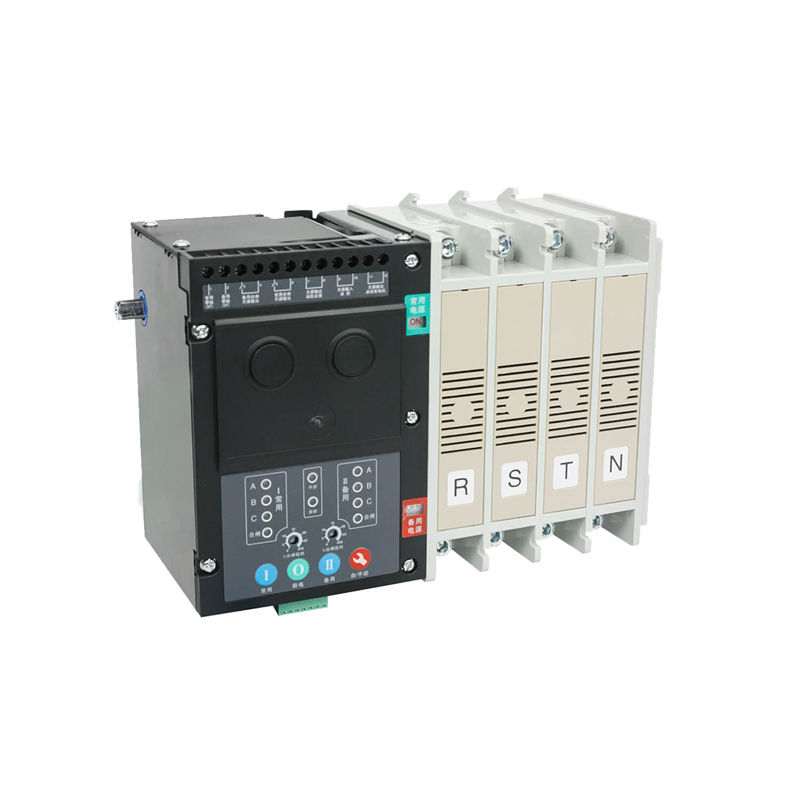
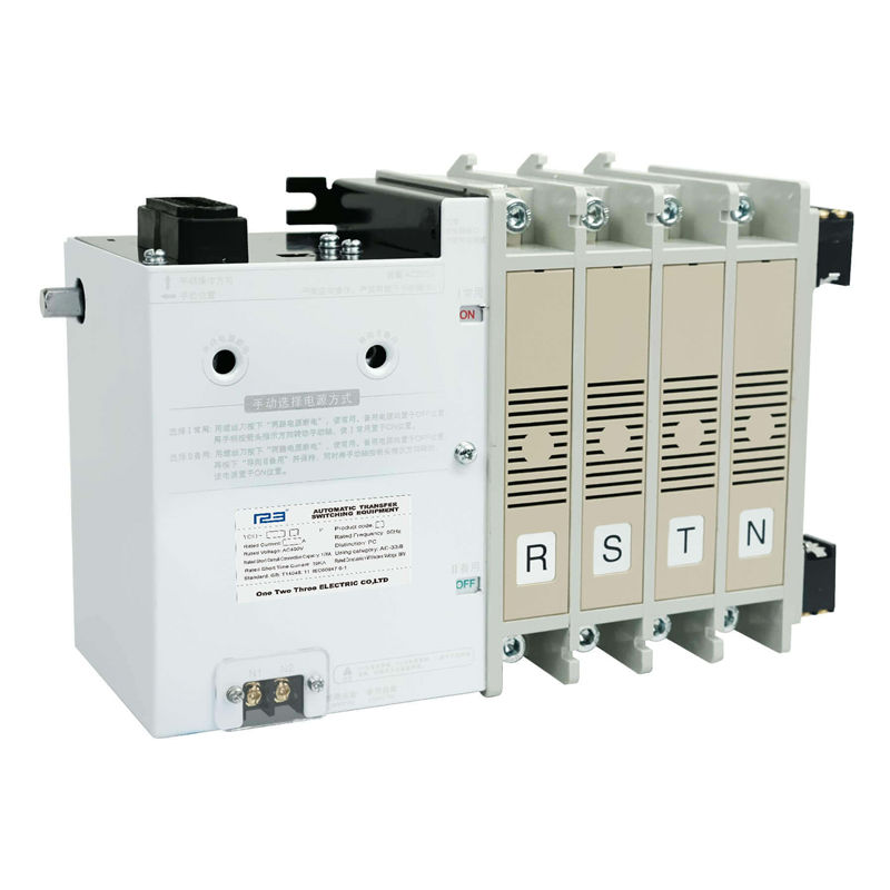
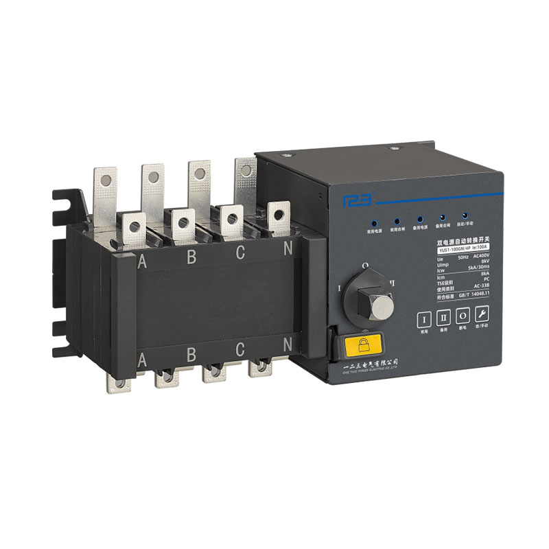
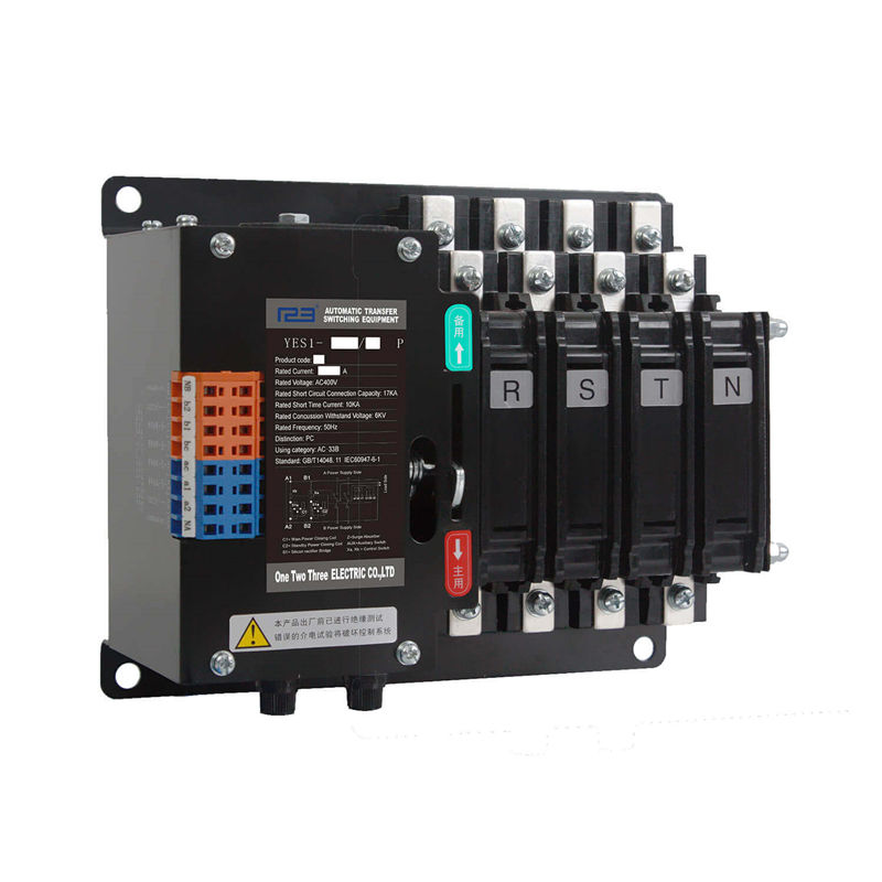
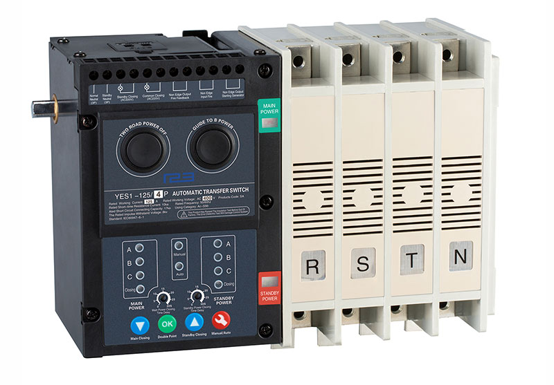
Is one of adopted international ATSE technology developed by our company. It is suitable for power supply system with rated working voltage is AC400V, and AC 50Hz/60Hz. Normally the power could be utility,auto start genset,storage battery and so on.
Rated current: 16A~630A
Pole: 2P,3P,4P
Automatic Transfer Switch Instruction Manual (without controller)
General
Automatic transfer switch is one of adopted international ATSE technology developed by our company. It is suitable for power supply system with rated working voltage is AC400V, and AC 50Hz/60Hz.
Automatic transfer switch is main used for high building,hospital,hotal and communication, coal mining,shipping,military facilities industrial assembly line etc the situation of need the continuous power supply.
Normally the power could be utility,auto start genset,storage battery and so on.
Notice:
1. L type is two positions. When switch get the switching signal,it will not stop at Off position,it will transfer to the other power source directly.
2. S type is three positions. When switch get the switching signal,it can transfer to the other power source directly,also can transfer to Off position.
3. Switch is PC Class.
4. Connect type is front panel connection.
Working conditions
1. Ambient air temperature: Ambient air temperature of -5 ℃ to +40 ℃, and at 24-hour average temperature does not exceed +35 ℃. If ambient air temperature above +40 ℃ or below -5 ℃,users should consult with manufacturer.
2. Atmospheric humidity: The maximum temperature of +40 ℃,the air relative humidity do not more than 50%. At a lower temperature can be allowed to have a higher relative humidity. Special measures should be taken for occasional condensation due to temperature changes.
3. Installation Altitude: The altitude of installation locations do not above 2,000 meters. For higher altitudes, please consult the manufacturer to take into account the reduced dielectric strength and cooling effect of the air.
4. Pollution levels: Installation on grade III
5. Installation category: Installation category IV type
6. Installed tilt: Products in the cabinet fixed installation, the maximum inclination is ± 22.5°.
7. Flashover distance: AC400V electric flashover distance is 30mm.
8 Use category: AC-33iB.
Product Parameters
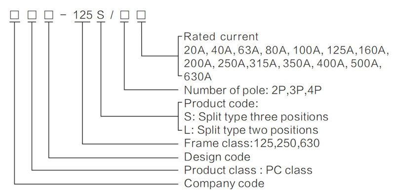
Products model and meaning
Technical parameter
| Model | S type, L type | ||||||
| Insulation voltage | AC690V | ||||||
| Rated voltage | AC400V | ||||||
| Rated current | 20A~125A | 160A~250A | 315A~630A | ||||
| The rated impulse withstand voltage | 8KV | ||||||
| Vote number | Double vote | ||||||
| Wiring manner | Before the board | ||||||
| Characteristic | Short time withstand current | 10kA | |||||
| Connect sub-capacity | 17kA | ||||||
| Service life | 1000/5000times | 1000/4000times | |||||
| Operating cycle | 60times/hour | ||||||
| Useing class | AC-33iB | ||||||
| Auxiliary switch | A、B side power both with 2 normally open and 2 normally closed; switch capacity 15A/AC250V | ||||||
| Accessory | Manual handle | ||||||
Connection diagram
Connection diagram of power indication and power ON indication.
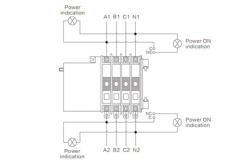
Three positions S type terminal function connection diagram.

Two positions L type terminal function connection diagram.

Appearance and installation dimensions
The safe distance dimensions of panel: 30mm(AC400V)
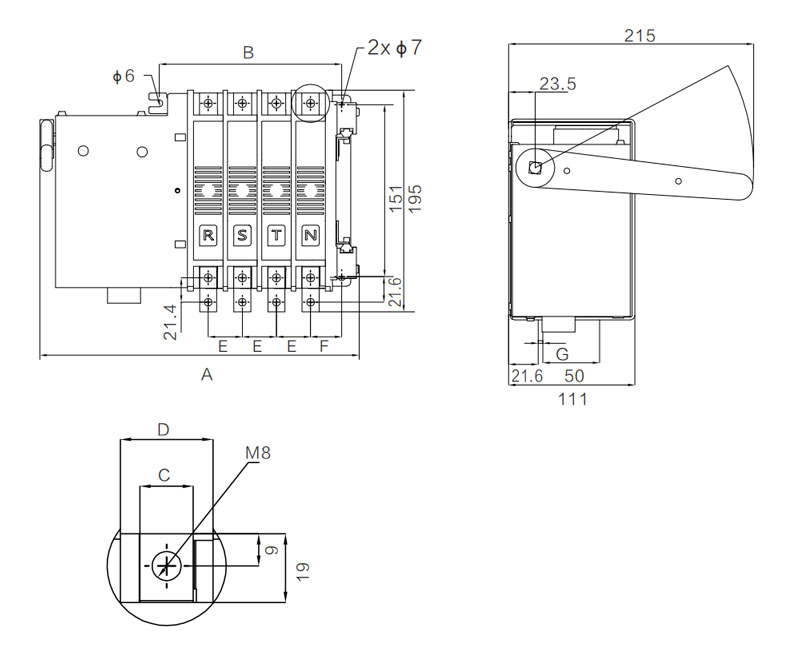
| Model | Pole | Dimension | ||||||
| A | B | C | D | E | F | G | ||
| 125S 125L | 2P | 223 | 100 | 15 | 26 | 30 | 27.5 | 4 |
| 3P | 253 | 130 | ||||||
| 4P | 283 | 160 | ||||||
| 250S 250L | 2P | 231 | 111 | 20 | 31 | 35 | 30 | 4 |
| 3P | 266 | 146 | ||||||
| 4P | 301 | 181 | ||||||
The safe distance dimensions of panel: 30mm(AC400V)
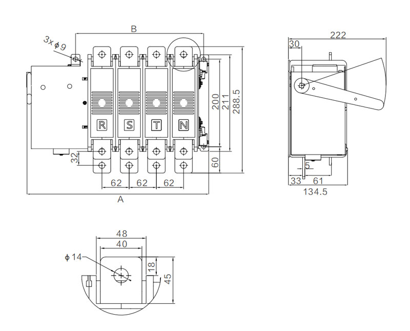
| Model | Pole | Dimension | |
| A | B | ||
| 125S 125L | 2P | 295 | 168 |
| 3P | 375 | 230 | |
| 4P | 419 | 292 | |
Product Choice
| Model | Type | |||||||||||
| YES1-63SA YES1-63LA3 | YES1-125SA YES1-125LA3 | YES1-250SA YES1-250LA3 | YES1-630SA YES1-630LA3 | |||||||||
| Insulation Voltage | AC690V | |||||||||||
| Rated Voltage | AC400V | |||||||||||
| Rated Current(Amp) | 16A~63A | 20A~125A | 160A~250A | 315A~630A | ||||||||
| The Rated Impulse with Stand Voltage(KV) | 8kv | |||||||||||
| Usingzation Category | AC - 33iB | |||||||||||
| Vote Number | Double Throw | |||||||||||
| Wiring Manner | Panel Mounting | |||||||||||
| Pole | 2P | 3P | 4P | 2P | 3P | 4P | 2P | 3P | 4P | 2P | 3P | 4P |
| Weight(kg) | 5 | 5.5 | 6.3 | 6 | 6.3 | 7 | 6 | 8 | 10 | 11 | 13.6 | 16.2 |
| Short Time With Stand Current | 10 KA | 12.6 KA | ||||||||||
| Connect Sub-Capacity | 6 le | |||||||||||
| Service Life | 6000/20000 | 1000/4000 | ||||||||||
| Operating Cycle(S/Time) | 60 times/h | |||||||||||
| Auxiliary | 1.II power:2 normal open.2 normal closed capacity:15A/AC | |||||||||||
| Accessory | Manual operating handle,division plate | |||||||||||
Precautions
Manual operation and matters need attention
The manner of I power input: Screwdriver press the "TWO ROAD POWER OFF", so I power and II power are both in the OFF position ( L type no need this operation). With a wrench to manually rotate the direction of the arrow shaft so that I power will place in ON position.
The manner of II power input: Screwdriver press the "TWO ROAD POWER OFF", so I power and II power are both in the OFF position ( L type no need this operation). Then press the "GUIDE TO II POWER" and hold, while manually rotate the direction of the arrow shaft so that II power will place in ON position.
The manner of artificial escape:(Only fit for S type, L type can only transfer and can't release) Remove manual operating handle, screwdriver insert the hole of "TWO ROAD POWER OFF" and press inward to escape.
Note :
1. Manual is forbidden when switch with load conditions, manual operation is allowed when the controller must be in manual or power-off state.
2. The handle must be removed after operation.
Maintenance and storage
Check and maintenance must be conducted by the professional personnel, inspection and maintenance should be cut off when all the external electricity power. In order to maintain the performance of the switch and continue to keep the switch in good state, the first maintenance check must within one year after installation, and maintenance regularly at least once a year.

